ERCES System Monitoring and Fire Alarm ConnectionsAre your ERCES to alarm system connections done correctly? Maybe not!
Posted on October 25, 2023By John Foley, Managing Director, Safer Buildings Coalition All ERCES must be monitored by the fire alarm system in accordance with the code/standard determined by the AHJ/Fire Code Official. It is important to note the requirements of the National Fire Alarm Code NFPA 72 as well. Monitoring by Fire Alarm Required – Codes and Standards References:
IFC and NFPA vary slightly, but the concepts are the same. It is essential to confirm what version of codes and standards the jurisdiction is enforcing, and to understand any local amendments. Following are variations on supervisory signal requirements: IFC 2021IFC 2021 defines the following as required automatic supervisory signals:
*Note – monitoring of the communication link is not a supervisory signal created by the ERCES. It is a trouble condition detected by the fire alarm system. This will no doubt be corrected in an upcoming code revision.
NFPA 1221 – 2019The system shall include automatic supervisory signals for malfunctions of the ERCES that are annunciated by the fire alarm system:
Finally, the communications link between the fire alarm system and the two-way radio communications enhancement system shall be monitored for integrity. Note that NFPA 1221 separates the defined supervisory alarms from the requirement to monitor the communication link for integrity. This is better language. NFPA 1225 2022The system shall include automatic supervisory signals for malfunctions of the ERCES that are annunciated by the fire alarm system:
Why allow a single (summed) supervisory alarm? Two main reasons:
Donor Antenna Malfunction? Signal Source Malfunction?
There is considerable debate among those in the NFPA, IFC, and UL 2524 technical committees on the subject of Donor Antenna and Signal Source malfunction. Cellular-based public safety networks (such as FirstNet) often use directly connected base stations as signal sources instead of donor antennas. So, a system might not have a donor antenna. In fact, some LMR-based systems are directly connected (such as sections of the BART system in San Francisco). Secondly, there are a variety of ways a signal source or donor signal could be compromised:
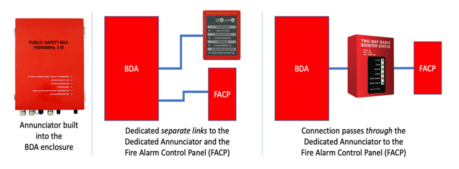
The signal could simply be degraded instead of cut. What constitutes a degradation worthy of an alarm? How do you handle the wide power swings in cellular services? What about analog LMR where there is no constant control channel (but UL 2524 requires an alarm after 200 seconds?). We have work to do! Dedicated AnnunciationThe purpose of a dedicated annunciator is to provide a local, visual, and audible indication of the health of the ERCES system. The dedicated annunciator should be located where the AHJ indicates. In some cases, in the Fire Command Center (if there is one), in some cases, in a continuously occupied area of the building such as the lobby. The annunciator must provide visual and labeled indications of the following (NFPA 1225):
Variations of manufacturer configurations:
Of these variations, the configuration using separate links to the dedicated annunciator and the FACP provides the most flexibility in locating the dedicated annunciator where the AHJ wants it – especially if it is far away from the fire alarm panel. Monitoring Communication Links for Integrity
Fire alarm systems commonly monitor communication links for integrity. There are four kinds of conditions the fire alarm system can detect:
Communication links are monitored for integrity by detecting trouble conditions. Trouble conditions are detected by the fire alarm system by using a nice little bit of basic electronics: the End of Line (EOL) Resistor. End of Line Resistor: Purpose, How it Works, Correct Placement, ResponsibilityThe purpose of the EOL resistor is to allow the Fire Alarm Panel to supervise the fire alarm field wiring for open or other fault conditions. This is also known as monitoring the circuit, or communication link, for integrity. How it Works: The End of Line (EOL) Resistor completes a circuit connected to a Fire Alarm System, establishing an expected value for current and voltage in the circuit. This allows the Fire Alarm Panel to distinguish among three states:
The placement of the EOL resistor is critical. It must be literally at the end of the line. In the case of ERCES, it should be as close as possible to the BDA, and if possible, inside the BDA. Current from the fire alarm system must not be able to reach the EOL resistor if the line is cut, or the alarm cable is unplugged. See the following diagram:
Responsibility:
Conclusion
As a life-safety system, the ERCES of course should be monitored for proper operation. But as illustrated in many cases above the codes and standards are not yet mature enough to cover every scenario. AHJs must work with system integrators (and vice versa) to arrive at technically rational, commercially feasible, solutions that accomplish the intent of the codes and standards while allowing for common sense and cost-consciousness. For extensive discussions of the codes, standards, and best practices related to ERCES monitoring, check out Chapters 5 and 25 in the Complete ERCES Handbook with NICET In-Building Public Safety Communications (IB-PSC) Study Guide. www.erceshandbook.com |


